HOME MODEL RANGE CONTACT US GALLERY VIDEO DOWNLOAD PRICE LIST
SAFEHAVEN MARINE. Builders of the Interceptor & Wildcat range of offshore craft
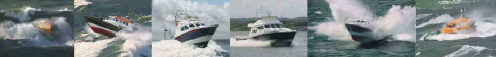
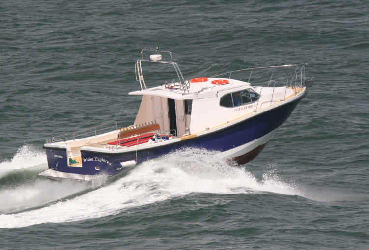
INTERCEPTOR 42 'Angling / Dive version'
DESIGN - The Interceptor 42 was designed by Frank Kowalski, who early in his career spent several years at sea skippering his own sea
angling charter boat off the South Irish Coast. The result of this experience is the Interceptor range and most relevantly this, the
INTERCEPTOR 42 ‘Angling Charter boat version’ Designed to fulfill many roles from high performance offshore cruiser to, big game fishing, and in this guise become possibly the definitive charter angling boat.To achieve this, a range of parameters were set, these being-
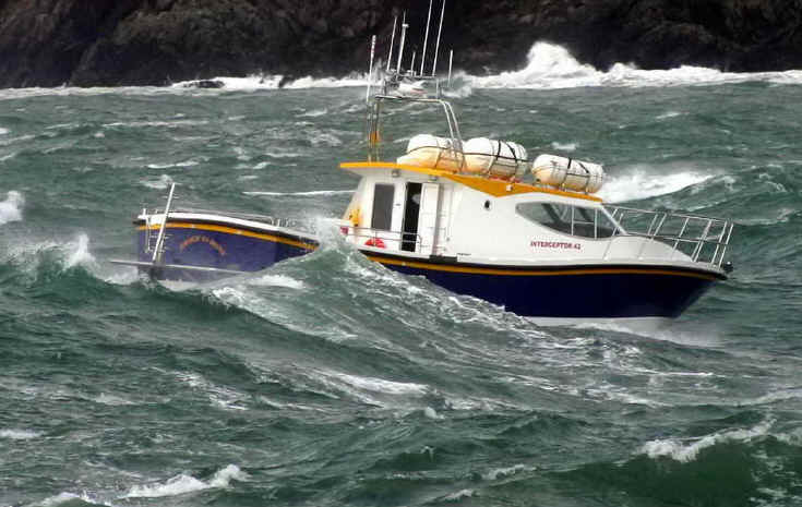
SEA KEEPING.- The endurance to maintain an operational speed of 16kts into a head sea generated by a sustained force 5 ,and run at
potentially higher speeds safely in beam & following seas. Her deep V hull with 22 degrees deadrise amidships, a fine 48 at the bow and
16 at the transom allows this, giving a soft ride with no slamming and exceptional directional stability with “hands off” steering in following
and quartering seas.
STABILITY- To provide a stable work platform.- A 13ft 10” beam makes her exceptionally stable, and hard chines & keel damp her motion, extending her operational envelope and increasing earning potential.
DRIFT SPEED- To give slow drift speeds and near beam on drift attitude, a very important feature when drift fishing allowing the anglers to stay in contact with the bottom and keep their lines separated. A deep full length keel provides this, giving good grip in the water as well as offering full protection to the stern gear.
ECONOMY- To provide higher than previously obtainable maximum speeds and allow for an economical cruising speed. Capable of turning a big 28” dia propeller in large (up to 700hp) single engine configurations providing, the maximum economy and engine longevity.
BOAT DRYNESS- Provide the operator with a dry ride. The unique twin chine hull gives with out question the driest ride available, increasing
visibility in poor conditions and reducing stress at the helm.
STYLE- To make the craft as beautiful and graceful as possible in order to lift the owner from the crowd and make him stand out in any port
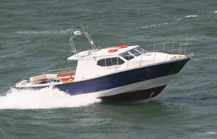
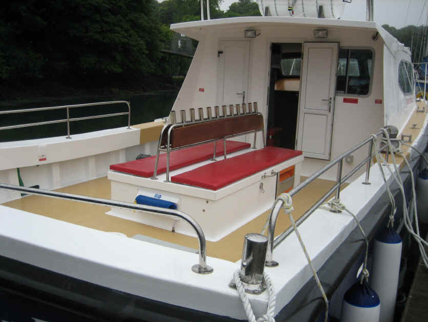
Her interior fit out is to a very high standard, fully lined and carpeted with high quality teak woodwork.
Our custom fabrication shop can build most things, here a stainless steel seating module combined with rod holders.
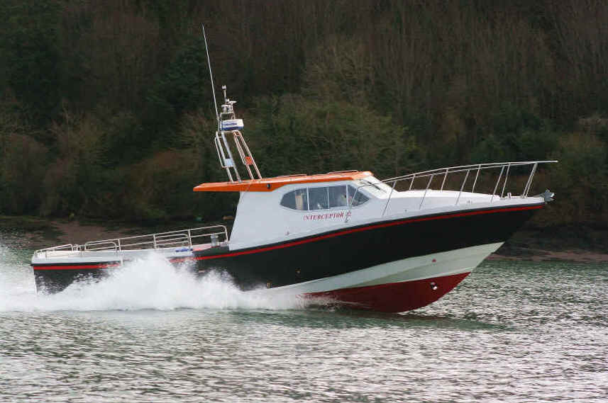
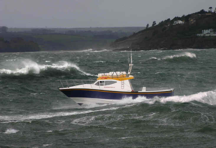
Below- The Interceptor has exceptional sea keeping abilities.
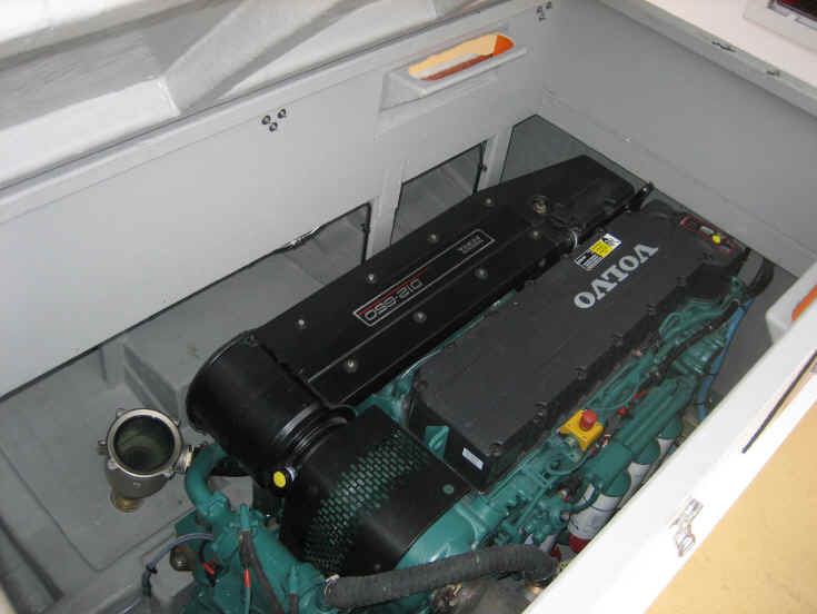
Below- the Volvo D12 650HP Engine, a very popular choice with customers.
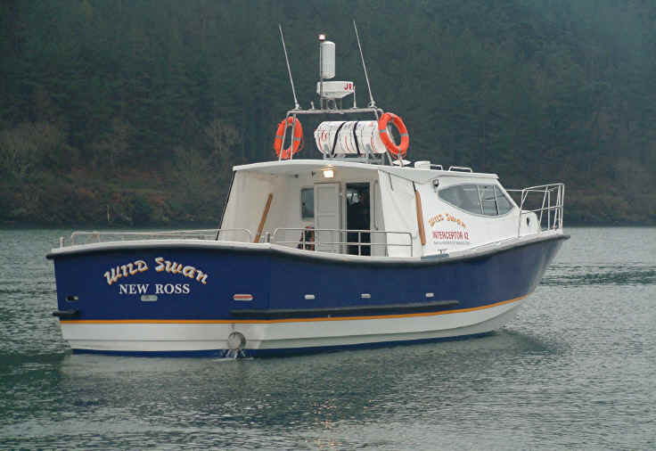
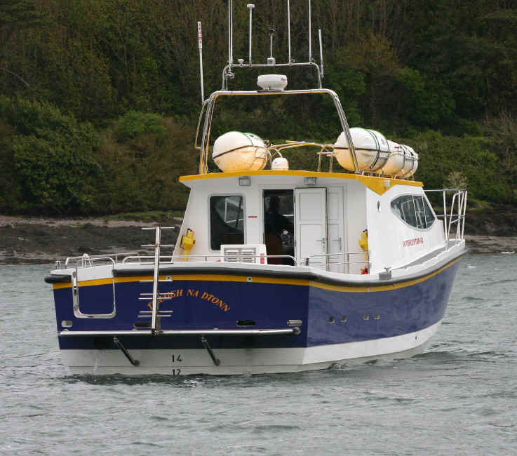
Below- Class 6 passenger vessel Toraigh na Dtonn, licenced for 40 passengers.
COMPLETED VESSEL SAMPLE SPECIFICATION
OVERVIEW
General
Description.
3
Classification
4
Principle
dimension
4
Speed
4
Hull
Construction
4
Deck
Construction
5
Wheelhouse
& superstructure construction
5
Bulkheads
6
Trails
& Delivery
6
GENERAL
ARRANGMENT
Fore
peak
6
Forward
Accommodation
6
Engine
Compartment
7
Wheelhouse
7
Aft
Peak
7
MACHINERY
Main
engines
8
Stern
Gear
8
Exhaust
system
8
Steering
System
8
Engine
controls and instrumentation
8
Skin
fittings
9
SYSTEMS
Bilge
systems
9
Fuel
tanks
9
Fuel
Gauges
9
Fuel
system
9
Engine
cooling system
10
Fire
extinguishing system
10
Fire
proofing / protection
10
Alarms
11
Fresh
water installation
11
Heating
11
ELECTRICAL
INSTALATION
Battery
Installation
11
Lighting
11
Navigation
and Communication equipment
12
Electrical
Equipment
12
Cathodic
Protection
12
FIT-OUT
Hull
fendering
12
Windows,
hatches and doors
13
Deck
fittings
13
Mast`
13
Handrails
14
MOB
Recovery system
14
Life
Saving equipment
14
PAINTING
External
colours
14
Internal
finishes
15
Logos
/ Lettering
15
ADDITIONAL
INVENTORY
Spares
/ Documentation
DRAWINGS
& DETAIL SCHEMATICS
LLOYDS
SPECIAL SERVICE CRAFT REPORT
1.
Overview
1.1
GENERAL DESCRIPTION
Vessel
Description.
The
Interceptor 42 is a GRP craft utilising a double chine Deep V Hull design. The
hull has a wide 13ft 6” beam providing high levels of transverse stability.
The deep V hull design with 22 degrees dead rise amidships, 47 at the bow and 18
at the transom gives excellent head sea performance with minimal pounding and
also provides safe and dependable down wind handling due to its cutaway fore
foot, and raked stem. The vessel is also very dry due to its double chine
arrangement and bow flare.
Service
history.
The
original craft launched in 2001 was a class 6 passenger vessel built for Martin
Oliver, Galway which was granted a licence by the Dept of Marine for 40
passengers. The vessel has been in service ever since and has proved an
excellent craft with her owners being very happy with her. Since then a further
18 craft have been built, the design has been very successful and is regarded as
having excellent sea keeping abilities by all owners. Built as a Pilot boat,
passenger vessel. Research and survey craft and commercial work boat.
1.
2
CLASIFICATION
The
hull and superstructure are to be moulded in general accordance with Lloyds
Register of Shipping (LRS) SSC Rules as applied to Vessels operating in area G3.
The Laminate weights and scantlings were determined using Lloyds Special Service
craft software, a print out is included in the appendix.
1.
3
PRINCIBLE
DIMENSIONS
Length
overall
44ft /
13.47m
Length
moulded
42ft 6” / 13m
Beam
moulded
13ft 4” / 4m
Beam
overall
14ft /
4.25m
Draught
4ft 2” / 1.28m
Displacement
(approx)
11,000kg (lightship)
1.
4
SPEED
The vessel shall
provide for an operational speed of 25kts fully loaded. (depending on engine
choice)
1.5
HULL CONSTRUCTION
Hull
laminate schedule / lay up wts -
300gm2
using isophthalic resin. Composite
as follows-
900gm2 CSM. isophthalic resin
900gm2 CSM. isophthalic resin
300gm2 CSM stitched in combination too
600gm2 Woven Roving
900gm2 CSM
300gm2 CSM stitched in combination too
600gm2 Woven Roving
900gm2 CSM
300gm2 CSM stitched in combination too
600gm2 Woven Roving
Total
shell laminate Bottom -
6600gm2
Hull sides
300gm2
using isophthalic resin. Composite
as follows-
900gm2 CSM. isophthalic resin
900gm2 CSM. isophthalic resin
300gm2 CSM stitched in combination too
600gm2 Woven Roving
900gm2 CSM
Sides
- 3900gm2
Reinforcement
- Keel. Additional 2 x 900gm2 CSM layers extending min 300mm from keel
across bottom. Each layer stepped back 25mm.
Keel -
8400gm2
Reinforcement
- Chines. Additional 2 x 900gm2 CSM layers extending min 10” up sides
& across bottom. Each layer staggered min 25mm
Chines - 8400gm2
No
coloring agent used in lay up.
No
longer than 24 hrs between layers to ensure chemical bond.
Immediately
after cure of main laminate & whilst still in mould the following stiffening
is bonded –
SCANTLINGS.
The
vessel is TRANSVERSLY FRAMED
at 500mm centres giving 400mm panel widths.
Transverse
frames- 100mm x100mm @ 500mm centers. Max
unsupported panel width, bottom –
450mm . side – 450mm. (measured between stiffeners)
Max span, bottom - 0.90m - 1.5m. side – 1.2m.
Lay up over frames
900gm2 CSM
900gm2 CSM
600 Unidirectional fibre on web face
Min overlap100-125mm
Longditudal Panel breakers- Foam cored 50mm deep x 100mm wide in section, lay up-
900gm2 CSM
900gm2 CSM
1800gm2
total laminate, staggered, min
overlap 150mm. Max span .45m
Main Longditudals- Foam cored 200mm deep x 100mm wide in section, lay up-
900gm2 CSM
900gm2 CSM
1800gm2
total laminate, staggered, min
overlap 150mm. Max span 2.5m
Engine girders - Wood cored (multiple layers plywood laminated together) 4” wide x 5-12” high.
lay up-
900gm2 CSM
900gm2 CSM
900gm2 CSM
2700gm2
total laminate, staggered, min
overlap 150mm. Max span 2.5m
1.6
DECK STRUCTURE
½“
plywood, gell coated bottom, encapsulated 900gm2 top. Supported on
4”x2” longditudal deck beams @ 16”/400mm centres. Bulkheads notched to
receive and bonded. Multiple vertical support beams & webs as per drawing.
Deck shelf foam cored as per drawing and bonded to hull 1800 gm2. Hull to deck
join - 1800 gm2, min overlap 125mm.
1.7
SUPERSTRUCTURE / WHEELHOUSE CONSTRUCTION
The superstructure consists of a GRP moulding, attached to the deck stainless bolts @ 8” centres and GRP internal angles (1800gm2 min 150mm overlap)
Laminate weights on superstructure are 2100gm2 - 3600gm2 laminate. Additional wood cored stiffening overlaid 1800gm2.
Main roof scantlings are provided by 30 x 75mm transverse frames @ 600mm centres across roof structure. All glassed into superstructure using 1800gm2 laminate with min 50-75mm angles.
Internal partition bulkheads & wood work (seating, lockers etc ) forming additional stiffening to structure which is al glassed into the side laminate.
Engine
vents are inboard along the inside of the gunwale.
Non slip deck coating applied to top side walkway.
The aft cockpit gunwale is a GRP Moulding of 2100gmw through bolted to the hull sides @ 150mm centres with GRP stiffening plates additionally glassed in approx 1,2m spacings.
1.8
BULKHEADS
Five
Transverse bulkheads as per drawings constructed from ½ ”/ 12mm plywood
overlaid 600gm2 per side with 50 x 50mm vertical webs to provide extra
stiffening. The b/heads are set on to the hull by being positioned on top of 50
x 50mm foam cored framing as per drawing to prevent formation of hard spots. And
are laminated to the hull using 1800gm2 laminate with a min 6” overlap.
Additional
collision b/head is fitted in the bow.
Materials
-
All Lloyds approved GRP materials (resin & glass) used in the construction of hull. Details provided.
1.9
TRAILS
& DELIVERY
On
completion and launch builders trails are to be carried out with an engine
manufactures representative aboard and the engine installation to be approved.
Customer
trails: Prior to hand over a full set of trails will be completed in Cork
Harbour and will include a two way run between the green and red buoys marking
the channel between the Oil Refinery and East Ferry in order to verify the
crafts maximum speed. Manoeuvring & handling trials
Will
be completed to determine the crafts
handling, and rough weather trails off Roches Point will be carried out to
determine the crafts sea keeping abilities.
A
full check on the operation of all the crafts systems and electronics will be
carried out.
All
trials to be carried out with 100% fuel, & 2 crew.
On
completion and acceptance of the vessel the craft to be handed over at East
Ferry Marina in
WARRANTY
Safehaven
Marine shall provide a 12 mth warranty against any defective workmanship or
component fitted to the craft. Equipment shall carry a 12mth warranty. The
Engine shall be covered by the engine manufacturers own 12 mth, or where
extended warranty.
2.1
FORE
PEAK
The
fore peak extends forward of the collision b/head and is a void space provided,
capable of being used as a storage area. There is full access to all fittings.
2.2
FORWARD
ACCOMODATION
Depending
on the chosen GA arrangement, but in general comprises a V Berth with 2”
cushions, The heads compartment positioned under the helm, there is a removable
hatch allowing access to all electrical components and fuses. The area is flow
coated white. A manual sea toilet is fitter with sea cocks exiting in the
compartment aft and being capable of easily reached for shut off.
The
galley can be positioned in this compartment, comprising 2 slide out teak
lockers, a 2 burner gas hob.
GAS INSTALATION
This
cooker is served from a dedicated gas supply with the gas bottle stored in the
aft cockpit in its own dedicated locker
which is vented overboard. The Gas run is in 10mm copper and uses correct
compression fittings throughout the installation.
Where
required a gas alarm is fitted with the sensor mounted low down in the bilge.
2.3
ENGINE
COMPARTMENT
The
engine compartment is accessed from the aft cockpit by either a W/Tight large
GRP engine hatch that is flush to the deck, or by an engine box with a raised
side coaming 320mm above the deck level, Hatches are securely closed when at sea
by an appropriate amount of locking mechanisms.
The
engine compartment is flow coated grey providing a smooth surface.
2.4
WHEELHOUSE
The
Wheelhouse has The helm position to port or st/bd, is fitted with a CAB 300
Series hydraulic damped and sprung
helm set on a pedestal. Adjustable for height and fore and aft adjustment.
The
cabin is fitted a 4 person dinette with table between. A L shaped bench seat is
opposite ists size being dependent on whether the heads is in the fore cabin or
the main cabin accessed from the aft cockpit. The layour will depend on the
chosen GA but will be similar to the above description.
The
floor surface is lined with studded rubber. An access hatch frovides acces to
the void space below.
2.5
AFT COMPARTMENT
Access
to this area is from a GRP hatch situated deck aft of the cabin entrance.. This
area contains the fuel tanks. Rudder and steering gear and exhaust outlets.
MACHINERY
3.1
MAIN ENGINES
The
vessel is fitted with a single Caterpillar 420hp engine and TWIN DISC MG5065A
gear box 2:1 ratio. Each engine is fitted with adjustable flexible mountings.
The engines are mounted on 125 mm thick wood cored engine beds bolted through
taped glassed in 12mm steel with 14mm bolts.
The
machinery is installed in accordance with the manufacturers recommendations and
installation instructions and commissioned by the appointed agent / engineer and
tested to provide conformity with the manufacturers recommendations.
Care
and attention is paid to providing durable machinery installation with adequate
support and neatness on all piping and cable runs. Special attention is paid to
provide ease of ongoing maintenance and ensuring all service items are readily
accessible. All piping and
connections to the engine and throughout the overall installation are to be of
an approved type.
3.2
STERN GEAR
Stern
gear is provided by Clements engineering in the UK, consisting of:
45mm”
stainless steel Aqualloy 30 or equivalent.
Glass
in P bracket with cutlass bearing
GRP
Glass in type stern tube assemblies with cutlass bearing
Drip
free PPS or equivalent water lubricated stern tube seal
Rudder
assemblies fitted with bronze blades, steering quadrants, O ring seals and PTFE
type bearing also packed with grease through nipple.
GRP rudder tubes, glassed in to hull bottom and reinforced as
appropriate. 38mm solid steel tie bar, 20mm ball joints with 20mm bolts through
tiller arm.
Square
rudder stock allows fitting of an emergency tiller arm through a deck opening.
R&D
coupling between the shaft half coupling and gearbox flange.
4
Blade 25” propeller.
3.3
EXHAUST SYSTEM
The
exhaust system is a wet type run from each engines exhaust and exciting the
transom via a Vetus exhaust outlet fitted with a non return flap. Vetus 6”
exhaust hosing with double stainless claps on each connection. The exhaust
system is designed to prevent back flooding of water to the engines and shall
meet all engine manufacturers requirements regarding fall and back pressure. 6
3.4
STEERING SYSTEM
The
vessel is fitted with a hydraulic steering system consisting of a Vetus MTP53R
Hydraulic steering helm pump. MTP 175 steering ram providing the craft with a
hard over to hard over of 6 wheel turns without being overly heavy in steering
effort. Fitted with a bypass valve to allow peration via the emergency steering
tiller arm. The system uses 10mm copper piping and compression fittings
throughout, with a section of flexible hose at the steering ram to absorb
steering ram movment.
An
emergency steering tiller can be supplied and stowed in the aft compartment.
3.5
ENGINE CONTROLS & INSTRUMENTATON
Single
lever Morse controls with cables fitted at the main helm positioned,
ergonomically positioned for ease of operation.
The
engine panel is fitted with the standard manufactures instrumentation
comprising-
Tachometer
Oil
Pressure gauge
Water
temperature gauge
Battery
voltmeter
(may
differ according to manufacturers spec)
3.6
SKIN FITTINGS
All
skin fittings used throughout the vessel are of a suitable marine grade material
and are fitted with ball type, lever operated shut off valve in the engine
compartment. All underwater valves are fitted with twin stainless steel jubilee
clips.
4.1
BILGE PUMPING SYSTEMS
The
craft is sub divided into four compartments..
Each
water tight compartment is fitted with one diapram type pump of 90 ltre p/m
capacity of 1 ½” dia piping.. Where a bilge run passes through a b/head it
does so through a s/steel b/head fitting as high as practicable in the b/head.
The bilge system exits the hull above the W/L via a shut off valve. Each pump is
clearly labelled for its operation.
4.1
FUEL TANK
Fuel
tank position is in the aft compartment outside the engine compartment. The
craft is fitted a Plastic fuel tank of approx 200 gallons capacity, to be
constructed from 12mm plastic welded, (or where required by rules as an option
of 2.5mm 304 grade stainless steel.) It is fitted on prepared beds in the aft
compartment and bolted to the aft engine room b/head and bonded attachment lugs
to the support beds (aft section of engine bearers, level and continued aft to
transom)
The
tanks are fitted with a suitable no of baffles, in general giving a maximum
unbaffled volume of 25 gallons
Each
tank is fitted with fuel take off and returns as well as venting. The fuel runs
use hydraulic hose from the tank to a through b/head hose fitting in the aft
engine room b/head, and from the other side to the fuel filters and on to the
engine with chrome plated copper piping. A short section of hydraulic hose runs
from the end of the steel pipe via a suitable fitting to the engine.
Fuel
fillers are positioned on top of the tanks and accessed via round inspection
hatches (150mm dia) on the aft deck. Fuel shut of valves are fitted here
(outside the engine compartment)
4.2
FUEL GAUGES
As
an optional extra each tank can be fitted with a sender unit and a fuel level
gauge at the helm console.
4.3
FUEL SUPPLY SYSTEM
Fuel
piping is of 15mm chrome plated copper or 20mm galvanised steel depending on
regulations applicable. Each tank is fitted with a VETUS WS720 series fuel
filter with a flow rate of greater than 180lt/hr and fitted with a glass bowl.
The system is arranged so that each engine feeds from and returns to its own
dedicated tank. A shut of valve is fitted in the aft compartment at the tanks.
4.4
ENGINE COOLING SYSTEM
Each
engine is cooled by a heat exchanger. The raw water is fed to each engine from
its own 2 ½” dia sea cock, fitted with an external grill and filtered by a
H/D Aquafax type (clear glass top) water strainer. The position of the raw water
intakes is carefully considered to provide a continuous supply of water to the
engines in rough conditions. Hose connections to the engine are double clipped
and the hose is of an approved fire proof type.
The
waste water from the engine is piped to the exhaust outlet elbow. A feed of
waste raw water is taken to the water lubricated stern glands. The feed from the
gland is in copper pipe and extends 400mm above the w/l, from which point it is
in suitable flexible hose to the engine.
4.5
ENGINE ROOM VENTILATION
Intake
air is supplied through a ventilation stack on the inside of the gunwale where
there is least spray. The vents are inboard facing, a dorade system is built
into the stack to prevent any water from entering the engine compartment. Air is
bought to the engine room down through a deck opening. A manually operated fire
flap is fitted allowing the engine room to be isolated in the event of fire. The
size of the ventilation is commensurate with the engine manufacturers
recommendations.
4.6
FIRE EXTINGUSHING SYSTEM
Fire-fighting
equipment.
Optional
extra, fitment at owners request.
·
A Co2gas flooding system is used to extinguish fire in the engine
compartment. Two 5 kg extinguishers (calculated by the recommended formula to be
suitable for the volume of the compartment) is situated outside the engine
compartment and are manually operated from the main cabin, outside the engine
compartment by means of a cable. The co2 gas is piped to the engine compartment
using 10mm copper pipe and compression fittings.
The
quantity of Co2 provided has been calculated to be sufficient to occupy at least
60% of the volume of the engine room compartment based on 0.56 cubic meters per
kg of liquid.
The main engine
room ventilation is positioned as per drawing. Of a size specified by engine
manufacturer. Situated on or about the vessels centre line with its opening
positioned .6m above deck level. Fitted with a closable flap manually
operated from the front of the ventilation box whereby the flap will close
off the engine room and allow the injected gas to extinguish the fire.
In the event of fire in the engine room the following provisions are made to prevent flooding.
The main raw water intake in the engine compartment uses fire proof exhaust hose to connect the engine to the sea cock via the strainer.
All
outlets in the engine compartment
use lever type shut off valves.
4.8
ALARM SYSTEMS
A
high level bilge alarm is fitted inside the engine compartment. An audible alarm
id fitted at the helm station. Automatic float level switches automatically
operate the bilge pumps in the event of flooding.
A
GAS ALARM is fitted where required by regulations. (optional extra)
4.9
FRESH WATER SYSTEM
The
craft is fitted with a 170 litre plastic fresh water tank. The system is
pressurised and distribution is by whale O’Ring type fittings and plastic
pipe. The tank is filled from a deck filler. The water tank also feeds a
windscreen washer system. (optional)
4.10
HEATING SYSTEM
A
hot air heating system is optionally fitted, a type whereby hot water from the
engine is used to heat a radiator and provide hot air trucked to the helm
station from where three adjustable outlets provide hot air to demist the
screens. A fourth outlet can be provided to the forward accommodation area.
ELECTRICAL
INSTALATION
5.1
BATTERY INSTALATION
The
electrical system is 12V. (24v optional) Two h/d batteries per engine fitted in
dedicated vented boxes inside the engine compartment, each fitted with a remote
operated solenoid isolator switch (operated from the helm) A parallel circuit
& isolator S/W fitted in the engine comp allows switching between battery
banks in an emergency should one bank fail.
A
second bank of two batteries fitted in a dedicated vented box under the f/wd
accommodation sole and is dedicated to service & equipment supply.
A
DC distribution board fitted with 16 circuit breakers / switches, one for each
of the main circuits.
All
cables are conduit run as required and all cables are securely clipped supported
and protected for operation in rough weather. All connections and junction boxes
mounted as high in the vessel as practicable and are of an approved marine
quality.
5.2
LIGHTING.
One
light in the forward accommodation area.
Toilet
light
Two
overhead quartz halogen lights in the main cabin
Single
Vetus round in the main cabin by door
Navigation
lights
Anchor
light
5.3
NAVIGATION & COMUNICATION EQUIPMENT
The
vessel can be fitted with an electronics package of the owners specification and
supply.
The
Radio equipment fitted will be to the licensing authority’s requirements, an
example is shown for approval purposes only
Raymarine
C120 plotter / 24N/M Radar combined
Simrad
DSSC VHF Radio
Hand
held radio
Depth
sounder / fishfinder
ERIPB
5.4
ELECTRICAL EQUIPMENT
One
pantograph windscreen wiper.
Vetus
water system pump
Bilge
alarm panel
5.5
CATHODIC PROTECTION
Anodes
of a suitable size are to be fitted, one per engine to provide a one year
service life. All sterngear is wired to the system and tested for effectiveness.
FIT
OUT
6.3
HULL FENDERING
As
standard 75x75mm H/D rubber fendering is fitted around the gunwale top. Bolted
with 6mm s/s bolts @ 150mm centres with a 5x50mm aluminium insert. Silkaflex
bonding adhesive is used in fitting the rubber to the hull. Optional heavier
fendering is available.
6.4
WINDOWS & HATCHES.
The
windows used throughout the craft are supplied by M.W.F. are of high quality
clamp in type utilising 6mm toughened glass and secured in place with silkaflex
and are fitted as shown on the GA drawings. Comprising:
3
front
2
side opening
2
aft cabin b/head
Single
escape hatch, Vetus type fitted overhead in the forward accommodation area.
The
main wheelhouse external door is of a H/D plastic design with corrosion proof
fittings.
6.5
DECK FITTINGS
All
deck fittings are fitted with backing plates. The following mooring arrangements
are provided.
One
large mooring bolard f/wd at the bow.
Two
large mooring bolards at the transom quarters.
Two
large midship spring cleats
A
bow roller is fitted at the bow
6.6
MAST
A
Stainless steel A frame type mast is constructed from 50mm s/s mirror polished
as per the GA drawing with mounting point for a GPS, Ariel and Radar.
6.7
HANDRAILS
All
external handrails are fabricated from 25mm dia 316 polished stainless steel
pipe and bolted to the superstructure with round backing plates with internal
concealed fixing (12mm bolts)
A
bow railing extended back as far as the end of the fore cabin. A single
horizontal rail is used.
A
railing extends around the aft cockpit to a minimum height of 1m above the deck.
A second horizontal rail closes the gap to a minimum width of 9”
Chain
closures are used by way of access breaks in the railings.
In
addition throughout the craft where necessary there are fitted a number of
vertical 25mm grab rails where necessary to allow for safe thoroughfare.
6.8
SCUPPERS /
COAMINGS
The
aft cockpit contains a number of
large scupper to clear any water on the aft deck. A minimum of two 250cm2
scuppers are fitted in the transom four additional scuppers are positioned
evenly along the vessels side. Where fitted the vessels engine boxes coaming is
320mm above the deck.
6.9
MOB RECOVERY
A
ladder can be fitted at the transom to allow access to the waterline.
6.10
SAFETY EQUIPMENT
Owner
supplied
Liferaft
of a type approved by the Licensing authority, capable of containing all crew
members fitted to superstructure roof and fitted with a hydrostatic release
system.
Owner
supplied
2
30” dia orange life buoys fitted with lights and one fitted with 100m line.
6
no Self inflating Dept of Marine approved life jackets
2
no Safety Harnesses
Boat
hook man overboard recovery pole
1
no Category C first aid kit
Offshore
flares in poly bottle.
PAINT
& FINISHES
7.1
EXTERNAL
FINISHES
Antifouling
Deck
Owners choice of non slip colour
Superstructure
Wood
2 coats mat varnish on woodwork
7.2 NAME
& LOGO
Owner
supplied
7.3
INTERNAL FINISHES
In
general all surfaces in the main cabin are carpeted where practical in blue or
beige carpet.
Otherwise
surfaces are painted in grey flow coat.
Headlining
is White foam backed vinyl on removable 4mm plywood panels.
The
forward accommodation is where practical carpeted otherwise surfaces are flow
coated grey.
The
for peak is flow coated Grey
The
heads compartment is flow coated white.
Woodwork
in general uses teak faced plywood with teak trimming throughout